Download SATSAGEN 0.5 and latest versions from this page:
SATSAGEN Download Page
Highlights:
- Works with:
- ADALM-PLUTO
- HackRF One
- RTL-SDR Dongles
- Simple Spectrum Analyzer series like D6 JTGP-1033, Simple Spectrum Analyzer, and so on.
- Video trigger, real-time trigger, and fast-cycle feature
- ADALM-PLUTO custom gain table and Extended linearization table for all devices
- Transmit from raw format files
- I/Q balance panel
- Waterfall
- RX/TX converter offset
- Video Filter average option
- Keyboard or mouse wheel moving markers
- Status Display
- The X-Axis CT and SU indicators
Choose the device
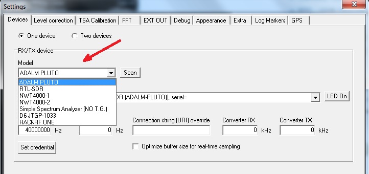
In Settings->Devices select the device model from the Model list control.
If one or more type model selected devices are present, these will be proposed in the below Device list.
If you connect a device at this time, press the Scan button to refresh the Device list control.
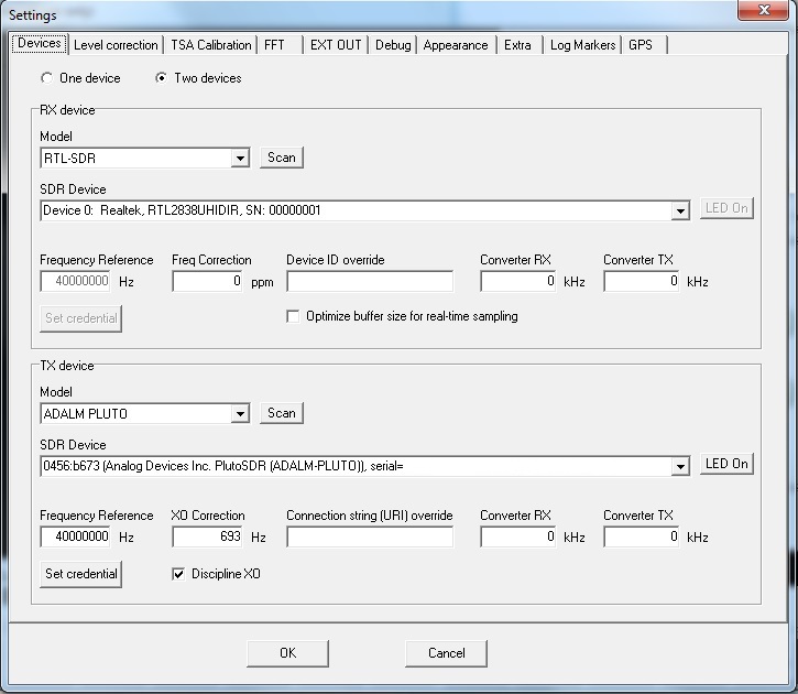
In a multi-device scenario, different RX and TX device model is allowed, with the one exception that the RTL-SDR device obviously can’t act as a TX device.
Video trigger, real-time trigger, and fast-cycle feature
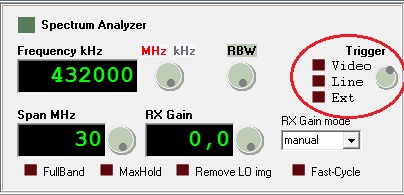
The Video trigger shows the spectrum graph when a signal of the minimum selected level occurs.
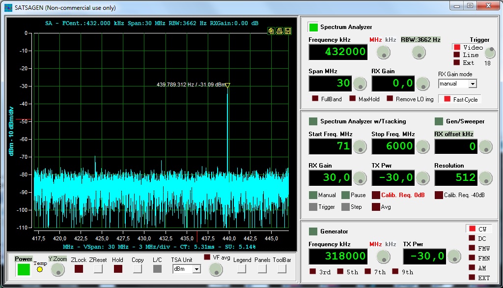
This is a random 4ms pulse caught by the Video trigger set at level 18. The Video level trigger is referred directly to the ADC depth value of the RX device.
The Line and Ext are real-time triggers, these start the acquisition when an external digital event occurs. With the knob select what type of digital event desire from Low, High, Chg, Neg, and Pos options.
- Low type starts the acquisition when the digital input is in a low state.
- High type starts the acquisition when the digital input in a high state.
- Chg type starts the acquisition when the digital input changes state.
- Neg type starts the acquisition at the falling edge of the input.
- Pos type starts the acquisition at the raising edge of the input.
Simple external hardware is required for the real-time triggers feature.
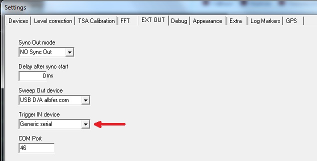
If a Generic serial is selected on the Trigger IN device control of Settings->EXT OUT tab, the Line trigger is mapped to DCD input of the serial specified by COM port control, and the Ext trigger is mapped to RI input of that serial COM port.
If a USB D/A albfer.com is selected on the Trigger IN device control of Settings->EXT OUT tab, the interface described on this page with FW version 2.0 can be used as a real-time input interface. The digital inputs are mapped like the above Generic serial on the USB D/A albfer.com interface, but an added feature of analog inputs can be used: the Line trigger is mapped to A0 input and the Ext trigger is mapped to A1 input. To enable this feature, click on the type title below the knob when a Line or Ext triggers are selected.
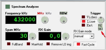
Now with the knob selects the analog level where the trigger starts the acquisition, with RE (rising edge) level or FE (falling edge) level.
To use the real-time trigger is required the Fast-Cycle set to on and the Optimize buffer size for real-time sampling checked (see on RX device controls on Settings->Devices tab).
The Line and Ext labels could be red blinking if the trigger fails to respond at the events in time.
Fast-Cycle
The Cycle-Time of the acquisitions (or Sweep-Time depending on the model of the RX device) is automatically tuned by the application to minimize CPU load according to sampling rate and FFT size selected by the user.
If the Fast-Cycle feature is turned on, the Cycle-time is fixed to the maximum speed of acquisition.
More speed performance (but with more CPU load) can be reached by selecting the SA uses CPU timestamp-based timer feature located in the Settings->Extra tab.
ADALM-PLUTO custom gain table
The ADALM-PLUTO standard gain table is optimized by ADI for the best RX noise factor in the whole range of frequencies. Unfortunately, the standard gain table doesn’t work as expected for spectrum analyzer operations because of the non-linear gain of LNA and for the table that is divided into three different ranges of frequencies.
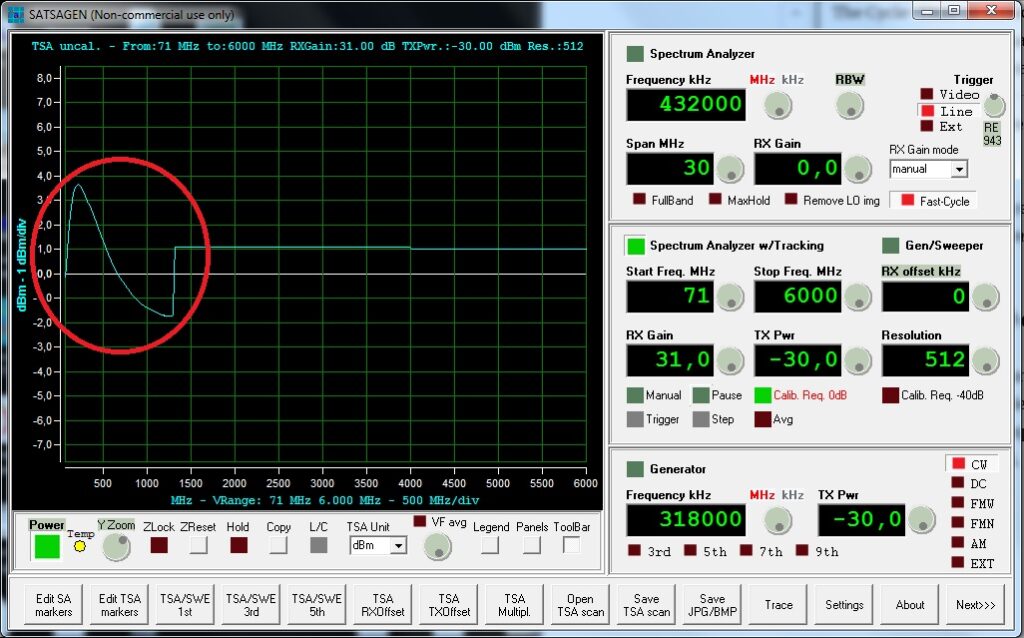
This is what happens with the standard gain table after calibration and moving from 30dB of RX gain to 31dB.
A flat frequency custom gain table is provided with the SATSAGEN distribution, it is located on the program directory as ad9361_CGT.
Add these lines to the RX linearization INI file to load the custom gain table on Pluto at the power on:
[settings\device_0]
PathNameCustomGainTable=ad9361_CGT
An extended RX linearization file is required to mitigate the non-linear gain of LNA in any case.
An extended RX linearization file model with the load of the custom gain table is provided on the program directory as curvecorrRX_PLUTOCGT.ini.
More information about compiling the extended RX linearization files will be published soon.
The standard gain table will be reloaded on the Pluto device at the power off of SATSAGEN to ensure the operation of other applications.
Transmit from raw format files
Open the EXT modulation panel from the menu or the EXTMOD Panel button of the Toolbar.
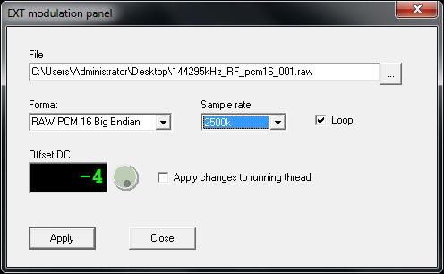
An only the RAW file is accepted. Specify in Format list the format to use to play the file and the sample rate according to the TX device selected capability.
If the Loop control is checked, the file will be transmitted endlessly until the stop command by the user.
The Offset DC value can be an aid to minimize the LO image residual component. Set initially to zero, check the control Apply changes to running thread and start TX streaming. During the reproduction, change the Offset DC value with the knob control until the LO image component reaches the lower position.
To start TX streaming of the file specified above, select the EXT modulation on the Generator panel and start the Generator.

The EXT label is red blinking when the thread is streaming.
I/Q balance panel
Open the I/Q balance panel with the context menu:
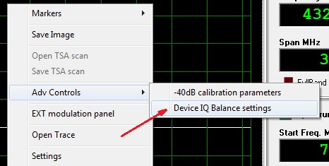
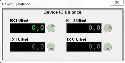
The Device I/Q balance panel is a tool useful to manually improve the quadrature of the RX/TX signal, especially when devices like RTL-SDR or HackRf are used.
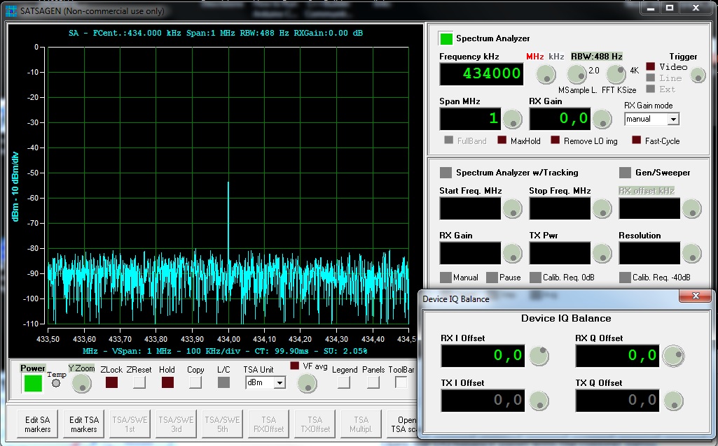
This is the LO component of the RTL-SDR dongle before the I/Q balanced is applied.
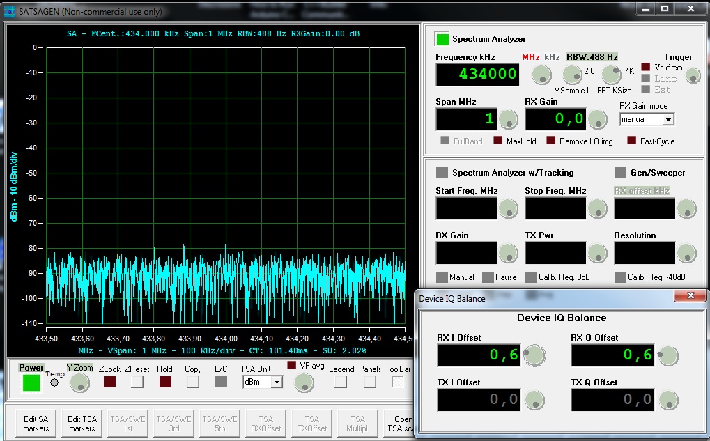
After the right I/Q balanced is applied, the LO component is almost at -80dBm.
The values of I/Q balance will be saved on devices configuration and automatically restored when the devices are connected and used.
Waterfall
When the Spectrum Analyzer is running, open the Waterfall with the context menu or the Waterfall button on the new tool panel opened by the panels button.
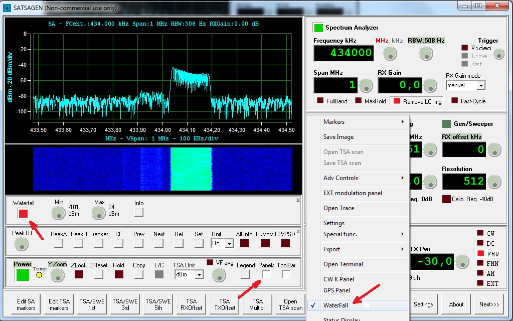
The Min and Max controls adjust the contrast of the Waterfall according to the signal level.
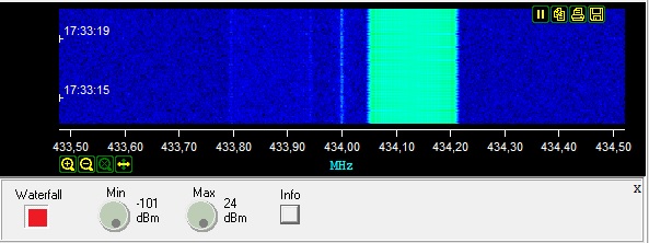
Click to Info button to adding the frequency and the time information.
RX/TX converter offset
If your SDR device has a converter, it could be useful setting an offset in SATSAGEN to have a matching frequency scale and input field.
Two fields in the Settings->Devices tab can be used to specify converters offset, Converter RX and Converter TX:
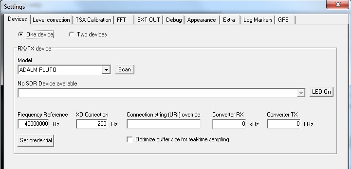
When a down-converter like an LNB is connected to the RX port, it should set the Converter RX field with the LO converter’s exact frequency with a minus sign. E.g., for a converter like LNB should be -9750000 kHz.
The rule for both fields is a minus value for a down-converter and a plus value for an up-converter.
Video Filter average option
The video filter normally operates to displays each measurement’s max value for the number of times chosen by the user. To switch to the averaging video filter, click on the little Led/button VF avg over the Video filter knob control.

Keyboard or mouse wheel moving markers
After a marker is placed, it can be moved by the mouse’s wheel or by the two keys J and K. This features works either in SA and TSA operations, but to activate it should be clicking on the window scope, and the marker to move should be active firstly.
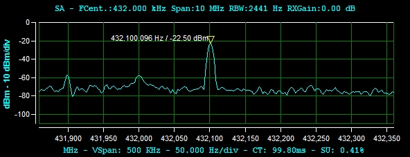
A marker was placed.
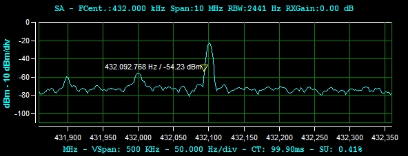
The above marker after pressing the J key three times.
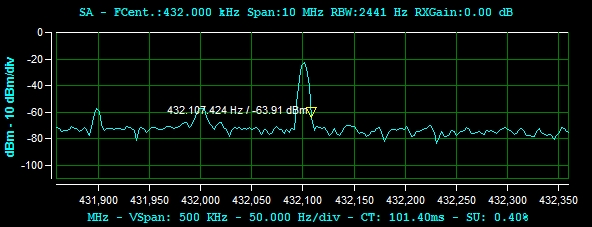
The same marker after pressing the K key six times.
Status Display
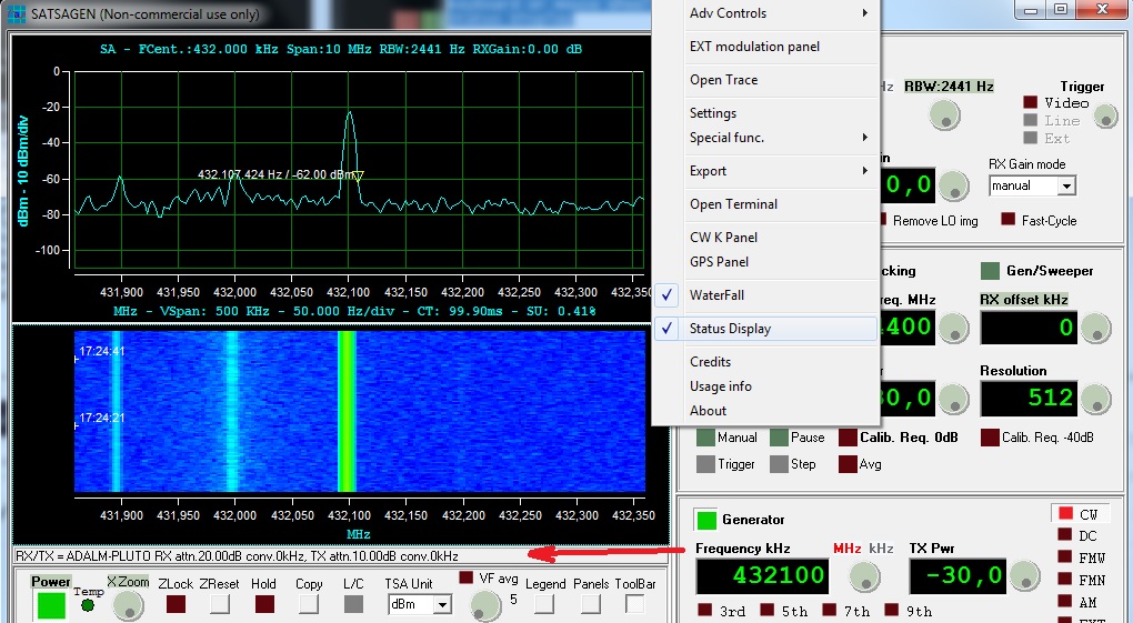
The status display shows some peculiar information about the active RX and TX devices. To activate this feature, click on the Status display from the context menu. For each device are displayed the type model, the attenuator value, and the converter offset value.
The X-Axis CT and SU indicators
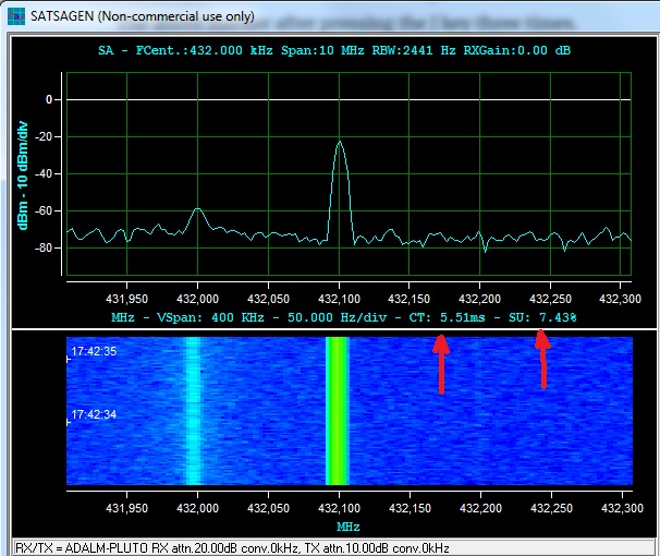
The CT indicator shows the Cycle Time of the SA. The Cycle Time includes the sampling time, the frequency switch time if the SA is in the swept-tuned mode, the Data computation and formatting time, and finally the display update time. For the SSA devices like the Simple Spectrum Analyzer, the CT is replaced by the Sweep-Time indicator.
The SU indicator shows the percentage of use of the stream from the SDR device. In the image example above, 7,43% of the sampling stream is used to display the spectrum.


Hello !
HELP
What is the config for HackRF. (With ZADIG you can recognize the RF One. But no display
Hello Franz,
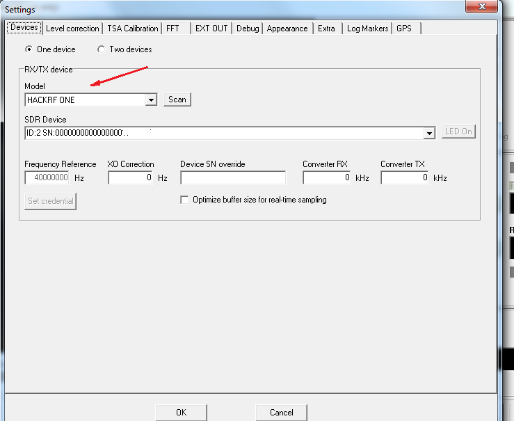
The config to using the HackRF should be simply select the HACKRF ONE model on the Settings->Devices tab:
Let me know
73, Alberto
Nice job! You should consider supporting Linux! Wine is not really an option…
Many thanks!
This is really good news! Though I’m now wondering whether you have any plans to support the LimeSDR in future as well?
Best regards
Hi,
Yes, I started developing LimeSDR support, but I need to buy the hardware to continue and carry out the tests.
Thank you!
Best Regards
Alberto
Hi Alberto
Did you get any further with support for the LimeSDR?
Cheers
John
Hi John,
Thank you for being so interested. I’m still working to obtain the hardware. Stay tuned.
Cheers
Alberto
Support Rtl_tcp or spyserver in future as well?
Yes, I hope in the next release.
Thank you!
Quella scheda! Indovino che e’ una scheda per Apple per un floppy di 8 polici??
Risate, avevo uno anche io!! Wirewrap!
Hi Peter!
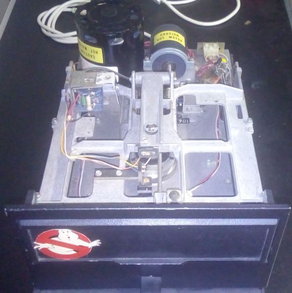
Yes, what nostalgia!
I borrowed the card from a friend of mine in the ’80, and I had wirewrap cloned it!
I used it with this drive that I still own:
Cheers
Alberto
Hello, Alberto.
Thank you for great software!
Maybe you will think about adding LimeSdr support? It will be great alternative for HackRf.
Best Regards, Sergii.
Hi Sergii!
Thank you for your comment!
I started developing the LimeSDR support, but I need to buy that hardware to continue.
Best Regards
Alberto
Really nice work,
Will SDRPlay RSP1 be supported ?
Best regards
Lasse
Hi Lasse,
I would like to support it, but I would need the hardware to make the linearization data and tests.
Regards
Alberto
Hi Alberto,
The MSI.SDR 12bit are quite cheap.
Anyway, a really nice work you done.
Regards
Lasse // SM6WHY
Yeah! Good info, Lasse!
Thank you!
Cheers
Alberto
Ciao Alberto
Very fine job with SATSAGEN 0.5. Thank you.
A feature request: On the Spectrum Analyser I use the ‘hold’ feature to capture a short burst of transmission. Would it be possible to allow markers to be placed on the hold trace as well as the ‘active’ trace? This would be helpful in recording the results.
Thanks
Bob
MM0MMQ
Hi Bob!
You talk about the max-hold trace, I think. Yes, placing markers on the max-hold trace could be useful. I’ll try to insert this feature in the next release.
Thank you so much!
Regards
Alberto
Grazie Alberto,
ottimo lavoro.
Nicola
Grazie mille Nicola!
Ciao
Getting this error. How to solve it?
14/02/2021 07:38:17 *** Power ON, please wait… ***
14/02/2021 07:38:17 Connecting to RTL SDR id 0
14/02/2021 07:38:18 Successfull connection to RTL SDR id 0
14/02/2021 07:38:18 Default device TX correction curve set due to a empty INI file for selected device(C:\Program Files (x86)\albfer.com\SATSAGEN\CurveCorrTX.ini)
14/02/2021 07:39:25 Failed
Hi!
Try to change the USB port. I noticed incompatibility with USB 3.1 ports.
Thank you!
Regards
Alberto
Hi Alberto,
Congratulation for this nice work.
Unfortunately the Terratec sdr Stick ( Elonics E4000 / RTL2832U) doesnt work (not detected) but it work very well on the last release of Airspy (SDR#)
The other stick R820T2 is well reconized and work fine.
Is there something extra to do for the first one ?
73
Jeff, F5BCB
Hi Jeff!
Thank you so much for reporting!
I’ll try to fix the Terratec dongle you noticed SATSAGEN does not detect that.
See you soon
73, Alberto
Hi Alberto,
Here is the response to rtl_test tool for my Terratec E4000 stick.
Frequency coverage is very large (52 to 2193 MHz) but there is some gaps.
73, Jeff, F5BCB
pi@r2cloud:~ $ rtl_test -t
Found 1 device(s):
0: Realtek, RTL2838UHIDIR, SN: 00000001
Using device 0: Terratec Cinergy T Stick RC (Rev.3)
Found Elonics E4000 tuner
Supported gain values (14): -1.0 1.5 4.0 6.5 9.0 11.5 14.0 16.5 19.0 21.5 24.0 29.0 34.0 42.0
Sampling at 2048000 S/s.
Benchmarking E4000 PLL…
[E4K] PLL not locked for 51000000 Hz!
[E4K] PLL not locked for 2194000000 Hz!
[E4K] PLL not locked for 1097000000 Hz!
[E4K] PLL not locked for 1241000000 Hz!
E4K range: 52 to 2193 MHz
E4K L-band gap: 1097 to 1241 MHz
pi@r2cloud:~ $
Hi Jeff,
Thank you again for the useful information!
73, Alberto
Bonjour Alberto, savez-vous si un utilisateur du pluto+ a fait un descriptif de cette solution ?
Ciao Alberto, sai se un utente pluto + ha descritto questa soluzione?
https://fr.aliexpress.com/item/1005002129182932.html?src=google&albch=shopping&acnt=248-630-5778&isdl=y&slnk=&plac=&mtctp=&albbt=Google_7_shopping&aff_platform=google&aff_short_key=UneMJZVf&&albagn=888888&isSmbAutoCall=false&needSmbHouyi=false&albcp=10191220517&albag=107473525088&trgt=743612850874&crea=fr1005002129182932&netw=u&device=c&albpg=743612850874&albpd=fr1005002129182932&gclid=EAIaIQobChMIyf-3n8Ov7wIV0O3tCh3YYw1JEAQYAiABEgKjN_D_BwE&gclsrc=aw.ds
Cordialement Jean-Luc F1GPA
Bonjour Jean-Luc,
Purtroppo no, spero che si possa fare una recensione a breve, mi sembra un prodotto interessante.
Grazie
73, Alberto
Hi Alberto,
do You plan to support Funcube Dongle for Satsagen software?
Vy 73
Werner DK1KW
Hi Werner,
Unfortunately, I don’t own a Funcube dongle. Maybe more important thing, I don’t found an API to control this device.
Thank you anyway for your suggestion!
73, Alberto
Hi, amazing tool..
I have an ‘idea’.
I am using a spectrum analyzer by R&S (FS300) without tracking source.
Do You think, it’s possible, to sync the SATSAGEN with the FS300 . to use the SATSAGEN as tracking source?
ehm, using the pluto
the fs300 has possibility for extern Trigger Sgnals. so , it would be ok, if at start of a new sweep of satsagen as tracking source, to get impulse from -for example- the output (tx) from comport , to trigger the fs300..
Hi Jens,
You can try it. From the Settings->EXT OUT tab, select the COM Port you want to use. From the Sync Out mode list select Start only. Pulses will be generated on the RTS line every start sweep of TSA or Sweeper Satsagen operations.
WARNING: Connect the serial RTS line to the external trigger signals port of your device only through a voltage translator interface; otherwise, there is a risk of damaging your device!
Alternatively, Satsagen can generate an analog sweep output. Set Sweep Out device on USB D/A albfer.com and connect this device: https://www.albfer.com/usbdaramp/#content
73, Alberto
Thank You ! Great, I will try & report.
I will share this thread in the satsagen mailing list.
Thank You fur the hint with voltage levels..
I am for work ‘Industrieelektroniker’ and working at a small company 5 minutes away from home (by feet) in the test-field or the department, which is building testequipment for our production lines . so, working with ‘levels’ is daily business 🙂
(www.rademacher.de)
kind regards &73 stay healthy!
Jens DL1LEP
Its really so usefull program, well done !
I have try it with a cheap RTL stick and also a usb RTL (starts from 100Khz).
Is it possible to go under 24 Mhz ?
Kind Regards&73
John (SY1BJV)
Hi John!
Thank you so much for your comment!
I’m sorry, the direct sampling on the RTL dongle is not supported yet.
We can start from 100kHz with HackRf or RSP1A/RSP1 devices for now.
73, Alberto
Great 🙂 I will try the HackRF.
i just got the HackRF One with portapack .
Hello Alberto,
It’s an amazing job. Thank you.
Do you have a plan to support the direct sampling on the RTL dongle or not?
(I have a HackRF, and rtl-sdr dongle. They work both amazing for filter test above 24Mhz. I need to test HF ones :)))
Hello Orkun,
Not yet. I would like to do it. I hope in the next version.
In the meantime, you could use an MSi SDR as an RX device if you have one of them.
Regards
Alberto
Hello Alberto,
Can I use upconverter with rtl-sdr dongle to reach the lower frequencies? By adjusting the converter RX parameter?
Thank you
73
Hi!
The upconverters for RTL-SDR, like a 125MHz LO model, can be used from SATSAGEN version 0.6.0.4, adjusting the Converter RX field to 125000 kHz from Settings->Devices tab.
Thank you!
73’s Alberto
Buongiorno, anche io ho un Hack , funziona bene ma non riesco a levare quei fastidiosi picchi periodici che genera penso il dispositivo…..sapreste darmi una soluzione?
Grazie per il grande lavoro!!!!!
Ciao Giovanni,
Se fai riferimento ai picchi periodici in corrispondenza della frequenza dell’oscillatore locale, in SATSAGEN puoi ridurli agendo sui controlli del pannello RX Device Balance settings apribile dall’omonima voce del menu Tools. Alcune istruzioni a riguardo le puoi trovare in questo articolo nel paragrafo “Pannello per migliorare la quadratura IQ per il dispositivo HackRF” https://www.albfer.com/2021/04/28/satsagen-0-5-3-4-2/
Un altro accorgimento importante che può aiutare a ridurre questi picchi anche usando altre applicazioni oltre a SATSAGEN è di accertarsi di avere una versione aggiornata del firmware HackRF.
Ciao
Alberto
Hi Alberto,
tried to connect my Newgen.RTL2832 SDR but it is not found by the scan function.
It works well with e.g. SpectrumLab and HDSDR software. Do I have to install a different driver?
Vy 73
Werner DK1KW
Hi Werner,
Thank you for reporting.
I’m sorry. I don’t think that driver updating solves this issue.
I’ll try to check this with a similar dongle. I’ll keep you update.
73, Alberto
Hi Alberto,
renewed the driver and now, the grid shows up on satsagen. When I start Spectrum Analyzer, I get this:
15.04.2021 18:02:35 *** Power ON, please wait… ***
15.04.2021 18:02:35 Connecting to RTL SDR id 0
15.04.2021 18:02:35 Successfull connection to RTL SDR id 0
15.04.2021 18:02:35 Default device TX correction curve set due to a empty INI file for selected device(C:\Program Files (x86)\albfer.com\SATSAGEN\CurveCorrTX.ini)
15.04.2021 18:03:01 >>>> standardSATimer return (-1)
Alberto,
sri to bother you. It works, obviously my USB port was too weak for the stick. After using one of a active hub NEWGEN works with Satsagen.
Many thanks for Your help.
Vy 73
Werner DK1KW
Great! Thank you for reporting your experience!
73, Alberto
Dear Alberto,
I’m in the early phase of using Satsagen for a variety of HAM Radio messurements.
I would like to messure the decoupling of an high power coax relais for EME use (> 70 better > 80 dB).
If my recollection is right I saw a discussion “how to use 2 Plutos …” to extend the measuring depth – but can’t find it anymore.
Can Satsagen do this job and does a “how to … guide” exist ?
Thank you very much !
Kind Regards,
Wolf
Hi Wolf,
There are some basics about dual device operations in this post: https://www.albfer.com/en/2020/10/11/satsagen-0-4/
Thank you!
Best Regards,
Alberto
Hello Alberto,
I was very happy when I found this software. Thanks so much for your hard work. Thanks to you, I can make my own filters 🙂
Would you consider adding support for the Ettus B200 in the future?
Kindly Regards
Zeki
Hi Zeki!
Thank you so much for your comment!
The Ettus B200 seems to be a great object. I hope to able to buy and support it in the future! Thank you for the tip!
Cheers
Alberto
hello, I can start the spectrum analyzer, but I can not power up the spectrum analyzer w/tracking or the generator function, any help is appreciated, ZI am new to this and trying my hardest to learn its operation.
thanks Hal . .
Hi!
Maybe your device is not able to transmit. Devices like ADALM-PLUTO are required to run spectrum analyzer/tracking or generator operations.
Cheers
Alberto
i wulld like to thank you ALBFER from the buttom of my heart –
i found satsagen usefull and professional to my taste
and i like the fact i culld take 2 devices and use them in a dual mode
without your help i culldnt efford any of that – the very fact that sasagen is free and professional
and it has features and support you culldnt find even in payed software
thank you for your great contribution .ALBFER
Noam, thank you so much for your comment!
I can’t get your nice software to work with my hackrf one r9. The device is not detected. Can you help? Thanks for your efforts.
Ash
Hi Ashley,
Can you send me the output of the Trace Log window?
– Connect your HackRF One r9
– Launch Satsagen
– Click on the Trace Log toolbar button
– Click on Settings
– Select HACKRF ONE from the Model list
– Click on the Scan button
– Click OK to close the Settings window
– Copy and paste here the output of the Trace Log window
Thank you!
Regards
Alberto