I received evidence of a 144 MHz bandpass filter characterization using SATSAGEN and ADALM-PLUTO from my friend Daniel DC2PCC.
Continue READINGAuthor: Alberto
SATSAGEN 0.5
Download SATSAGEN 0.5 and latest versions from this page:
SATSAGEN Download Page
Highlights:
- Works with:
- ADALM-PLUTO
- HackRF One
- RTL-SDR Dongles
- Simple Spectrum Analyzer series like D6 JTGP-1033, Simple Spectrum Analyzer, and so on.
- Video trigger, real-time trigger, and fast-cycle feature
- ADALM-PLUTO custom gain table and Extended linearization table for all devices
- Transmit from raw format files
- I/Q balance panel
- Waterfall
- RX/TX converter offset
- Video Filter average option
- Keyboard or mouse wheel moving markers
- Status Display
- The X-Axis CT and SU indicators
WSDRTEMP
Based on a Siegfried DG9BFC idea, this application shows the temperature of the TRX and the FPGA of ADALM-PLUTO in real-time.
Continue READINGSATSAGEN 0.4
Download SATSAGEN 0.4 and latest versions from this page:
SATSAGEN Download Page
Highlights:
- Dual device mode
- Generator with LO frequency output
Dual device mode
From version 0.4.0, SATSAGEN can handle two devices. In this dual device mode, the first device defined act as RX and the second as TX.

This mode improves the dynamic range of the system because it eliminates the internal crosstalk of devices.
Dual device mode settings
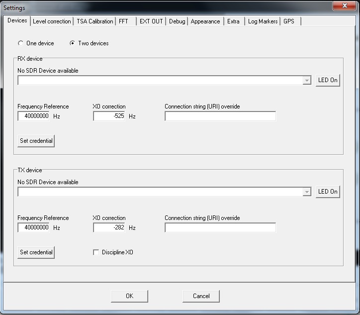
To enable this mode, select Two devices on tab Devices in Settings and specify the device that will act as RX in the first pane and device that will act as TX in the second. If neither devices are specified and the fields Connection string override are left blank, the default URI will be used for devices. The default URI for the first device is ip:192.168.2.1 and the second is ip:192.168.3.1.

If you have changed the default user and password of devices, you can save these on the program in safe encrypted mode, click buttons, and set credentials. These credentials will be used for sending commands useful to identify the devices uniquely. For example, these credentials will be used by the program to sending the commands to reverse the activity Led blinking of the devices when buttons Led On will be clicked. With buttons labeled Led On you can easily identify a device, the Led activity normal blinking of the related device will reverse.
The settings of the TX device in dual-mode have a checkbox labeled Discipline XO; if checked, the TX device is tuning with periodically XO correction values according to the position and shaping of the signal received in the dual-mode by RX device. These corrections are running during the scans and calibrations only with appropriate RX amplitude. This feature aid in mitigating the drift of the standard TCXO. Without this feature, the drift of standard TCXO in dual device mode can considerably affect the amplitudes read during the scans.
The feature Discipline XO is not active when:
- Frequency is below 71 MHz
- RX or TX offset are specified.
- The TSA scan modality is in multiplier offset or harmonic.
- The RX amplitude drops below -20 dBm for the fine correction according to signal shaping.
- The RX amplitude drops below -60 dBm for the correction according to the signal position.
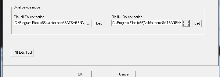
The tab Level correction has a new section in dual device mode where can be specified the custom linearization files for RX and TX devices running in this modality:

Dual device mode operation

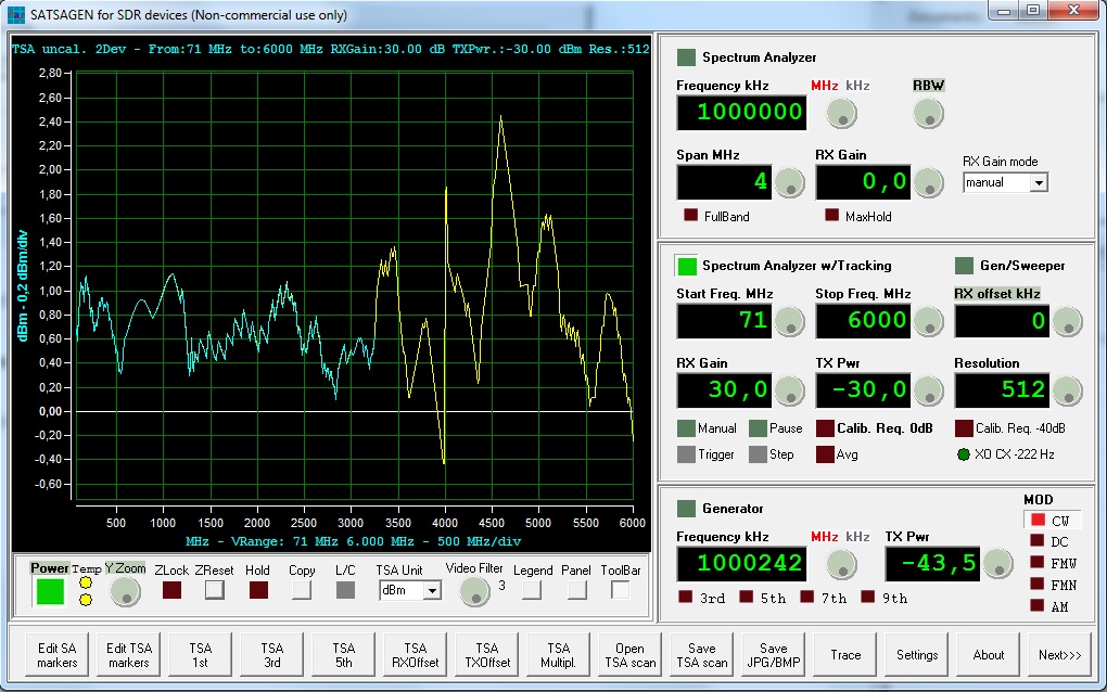
The dual device mode operation is the same as a standard single device; also, the user interfaces not change. The only difference is the small virtual LED in the right lower of the panel of TSA. This LED indicates the Discipline XO feature’s status with green color when normal condition and displays the value used for correction, in this example, -222 Hz.
I suggest before to do a calibration and execute the measures, to let running for some scans with a loopback cable. This trick allows the Discipline XO feature to reach the optimal correction for the TX device.
The best condition is reached when the temperature of devices is in steady-state, mostly when the devices use standard TCXO components.
Generator with LO frequency output
Set the generator to DC to turn off the modulation of the carrier:

This feature improves the generator output; moreover, the harmonics can be easily calculated because the output frequency is the same as the TX LO. In this mode, a DC is applied to the I and Q input of the TX mixer.

